Last update: September 28th, 2025
December 28th, 2024
Passive Deployment Mechanism for Base Camp on the Moon and Mars
森に棲む月に棲む / 月および火星に構築するベースキャンプのパッシブ展開構築法
Jun Sato / The University of Tokyo
佐藤 淳 / 東京大学
重力天体の構築物に必須となる「高床式」で「パッシブ」な展開構築法
月や火星に必要となる構築物および観測機器には「非平坦地」に「高脚」で「高床」を支持することが必須となります。
そこでこれを「パッシブ」に展開する「構築法」を提案します。
そして質量わずか数kgという極小型実証機での月面実証を目指しています。
この構築法で次のような難題を解決できています:
非平坦地に馴染む脚部による接地機構
ランダーからのリリース機構
インフレータブルモジュールの長径化
インフレータブルモジュール内の高床の構築
インフレータブルモジュールの外皮とエアロック部の接合
These solutions are included in our development:
Mechanism to touchdown on the bumpy terrain.
Mechanism to release a module from the lander.
Mechanism to build the floor in the inflatable module.
Fastener to connect the envelope and the airlock.
This base camp project is not officialized yet and is not an actual project in Japan.
We are looking for a way of international collaboration.
極小型実証機のセットアップ / Pilot module setup → Movie
極域へのセットアップ / Lunar pole setup → Movie

月の縦孔へのセットアップ / Lava tube setup → Movie
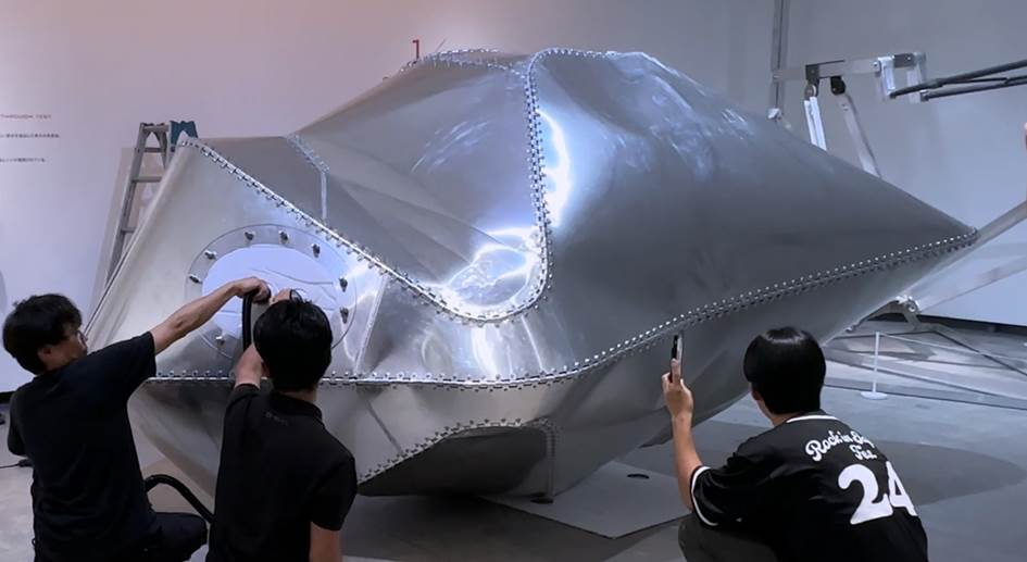
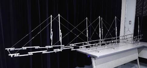
アルミ製の枕型多面体の実大モックアップの展開試験, S=1:1
Deployment test, full scale aluminium polyhedron for a habitation module, S=1:1
→ Movie
Tiny Pilot module / Small Pilot Module
重力天体の構築物を代表する形態の「All-in-oneモジュール」の極小型実証機
極小型実証機 → 目標質量4kg程度
少し大きな小型実証機 → 質量60kg程度
構築物を代表する要素として「非平坦地への接地脚」「高床」「金属製多面体」「発電」を備えます。
「非平坦地」で姿勢を保つ機構は「鉛直水平」を要求する観測機器の設置を簡素化することもできます。
「カンジキ型」のフットパッドがレゴリスを踏む挙動を観察して地表環境を取得することもできます。
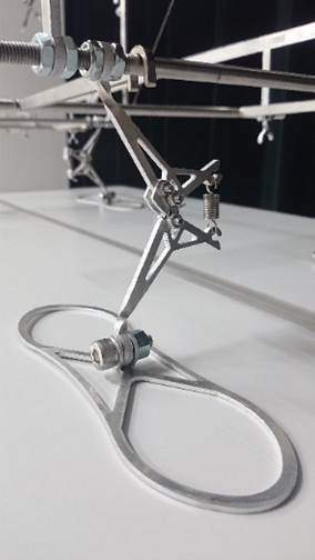
「振子機構」により姿勢を保つ着陸脚/特許出願中
鉛直、水平をとる必要のある小型観測機器に適用できる。
球状歯車の表面を滑る歯車ホイール

落下途中の任意の高さでロックされる落下脚/特許出願中
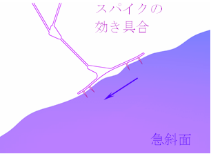
「カンジキ型フットパッド」とその接地シミュレーション
フットパッドの接地状態
斜面の場合や岩石(ボルダー)を踏んだ場合の滑動挙動
スパイクを設けるときの効き具合
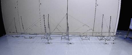
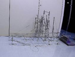
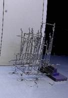
![]()

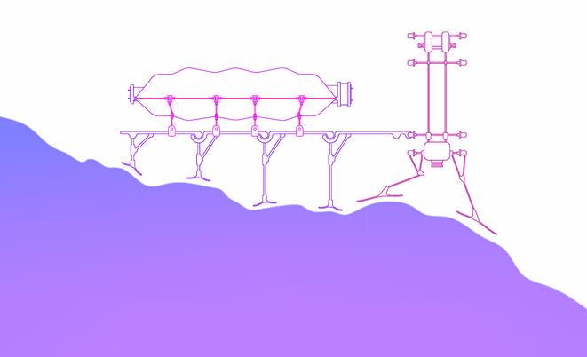
高床レールの第 1 ユニットが押し倒されるのと同期して脚部が接地する。
第 2 ユニットが片持ち状に引き倒されるのと同時に束が立ち張弦が張られる。
輸送機からの小型実証機のリリース
非平坦地に馴染む脚部機構が活用できる。
将来の発展:落下式設置
着陸前に周回中の輸送機から「放出落下」させる方式。
「パッシブ」に「非平坦地」に馴染む脚部機構が活用できる。
スラスターにより自力で減速させる必要はあるが燃料を少なくできる。
地球からの妨害電磁波を避ける月の裏側も含め各地へ設置できる。
モジュールの小型モックアップ
滞在モジュール / オーバーハングモジュール / ソーラーモジュール, S=1:10
Habitation module / Overhang module / Photovoltaic module, S=1:10
この展開構築法では、アクチュエーターによる「アクティブ」な機械制御を少なくし、スプリング等を利用して「パッシブ」に展開する機構であり、故障の少ない構築法とすることを目指しています。
レゴリス回避などのために居住部などに望まれる高床形式の構築法の確立は世界的に「難航」していますが、それを特定したものともなっています。
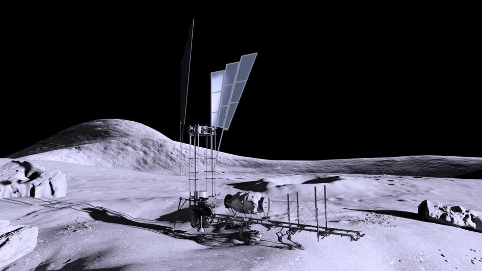
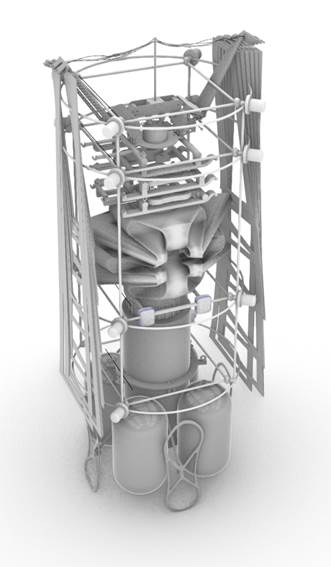
「非平坦地」に馴染む脚部、モジュールが載る「桟橋」、居住部となる「金属製インフレータブル多面体」、太陽電池を掲げる「ウイング」を一体化し「物資」も内蔵した「オールインワンモジュール」で構築物を代表して設計試作を進めています。
All-in-one setup for two crew members on the lunar pole
2人用のAll-in oneモジュール
まずは月の極域の昼間3週間前後の滞在を目指します。
構造解析モデル
![]()
![]()

本提案で開発するモジュールの居住モジュールおよびコロニーへの進展
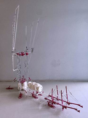
重力天体の構築物を代表する形態の「All-in-oneモジュール」の展開動作
「科学観測機器」および「高床式住居」の躯体に必要となる主な要素を一体化した極小型実証機
「輸送機からの荷卸 → 非平坦地への接地 → パッシブ展開」をトータルに現実化する。
![]()
![]()
![]()
![]()

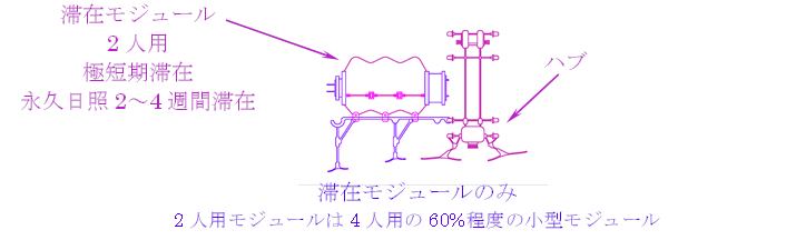
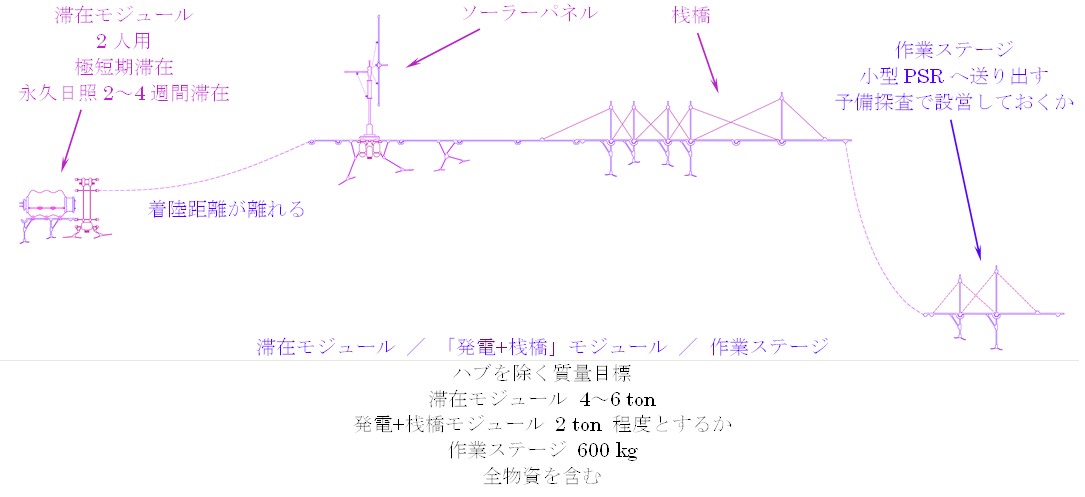
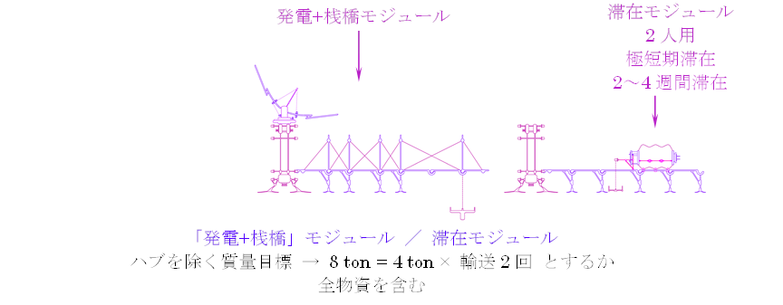
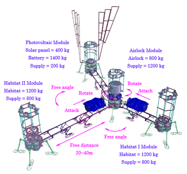
各機能を別輸送とし連結する概念図 / イメージ図
気圧調整室、発電部、居住部を分けて輸送する。
気圧調整室を「ハブ」として 2 人用の居住部をドッキングさせる。
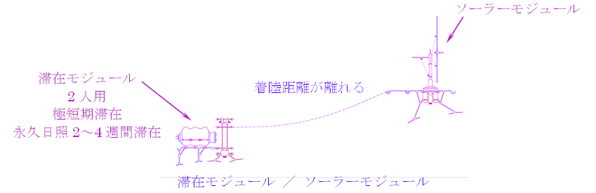
着陸精度および着陸時のレゴリス飛散に対する近接距離を考慮して離間距離を20〜40mとする。
誤差のある着陸位置から「フレキシブル」に連結できる。
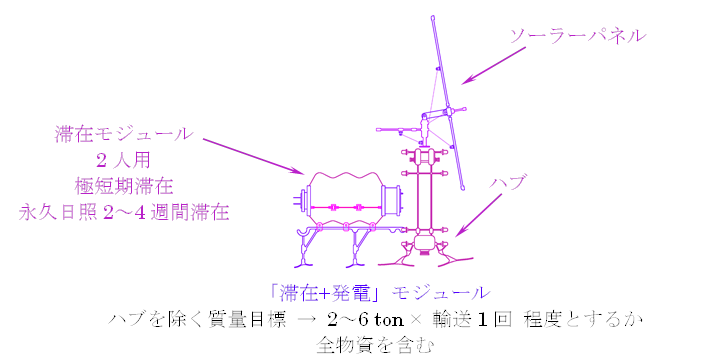
各部質量のイメージ
フレキシブルに変形できる曲線折り多面体
「フレキシブル」に着陸したモジュール同士をドッキングする。
2基の連結で「フェールセーフ機能」を確立することもできる。
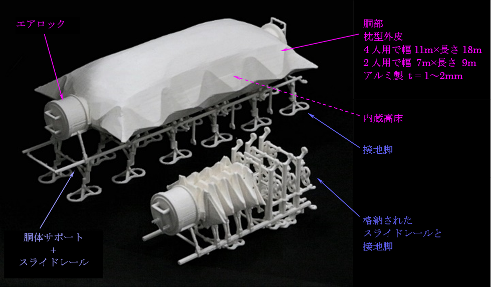
Components of a habitation module
居住モジュールの展開状態/格納状態
Embedded floor
外皮と「同時展開」する「内蔵高床」
Folded metal polyhedron using curved creases
Sakura dimples
小型モックアップによる展開実証 S=1:10
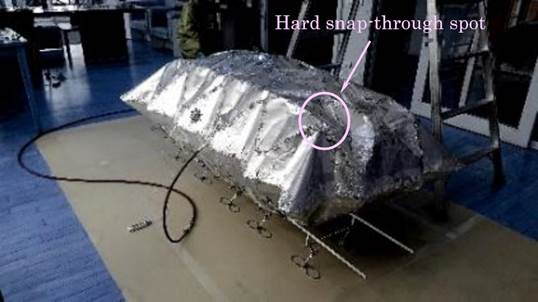
Hard snap-through spot on the overall envelope
Partial polyhedron extracted from the envelope
Partial polyhedron full scale mock-up, S=1:1
Material : Aluminium alloy A5052-H34, t=2.0mm
Deployment Test, Partial polyhedron, S=1:1
Maximum inner air pressure = 0.20 atm
Hinges for the curved crease, S=1:1
曲線折りのアルミ製多面体の展開挙動に追従するアルミ製の「ファスナー型ヒンジ」
「金属板同士」を接合することができる。
Support beam lifting up the envelope
Support beam full scale mock-up, S=1:1

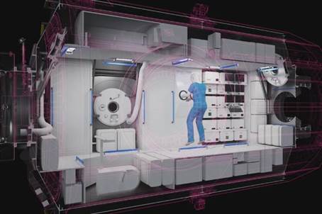
2 人用居住モジュールの内部建築計画
シリンダー部に装填されていた物資を引き出してしつらえた様子。
枕型外皮、シリンダー部の規模が概ね適正なことが判明しつつある。
Floor plan showing the cylinder filled with the supplies

Elevation showing the cylinder filled with the supplies
Attachment of radiation shield and insulation

Interior arrangement for 4 crews option including dense vegetation
(Provided by Takenaka Corporation)
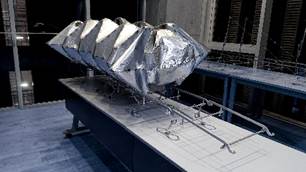
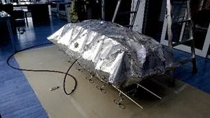
A single unit of the overhang module image
Overhang module full scale mock-up, S=1:1
Locking mechanism at the bottom of the strut


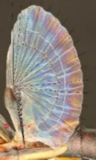
Solar power module provided in 2022, S=1:10 / Earwig’s wing

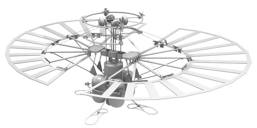
Solar power module, full scale partial mock-up
3-hinge bracing holding three fanning panels
International Astronautical Congress (IAC), IAC-2024, A3, IP, 223, x88668
1: Lunar pole / Lunar Pit
The lunar pole is assumed to be the target site for the beginning phase of human habitation due to its sunny spot suitable for the photovoltaic system and the permanent shadow region (PSR), which is expected to be the low radiation site. The lava tube in the pit is considered another favorable site due to its protected environment from radiation, the meteorites, and the temperature gap.
The composition of a base camp in the pit and the semi-passive deployment system for the primary structure of the components have been indicated in the past [1, 2, 3, 4]. Hereafter, taking a more compact setup into account, each deployable mechanism is updated through a full-scale mock-up, and a tiny module for a pilot exploration is developed.
This base camp project is a part of the STARDUST Program in Japan, but it is not officialized yet and is not an actual project, so we are looking for a way to collaborate internationally.
2: Lunar pole setup
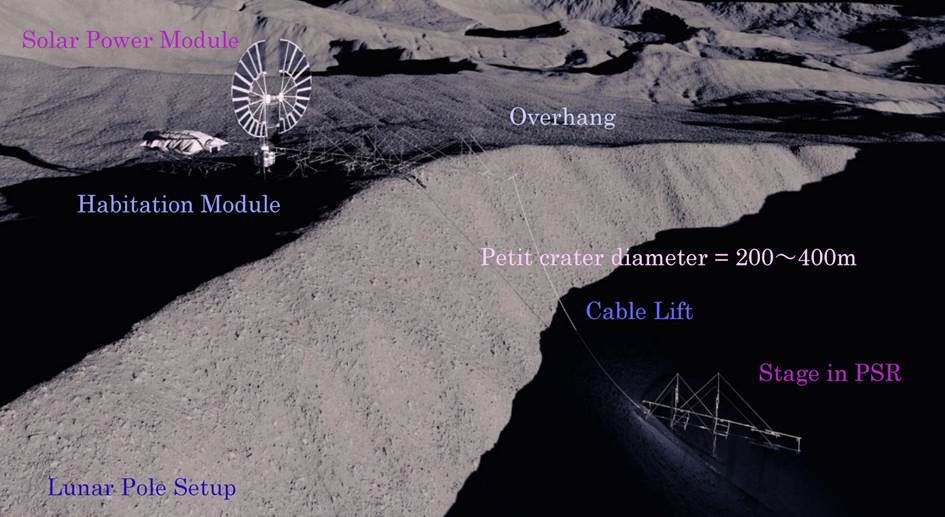
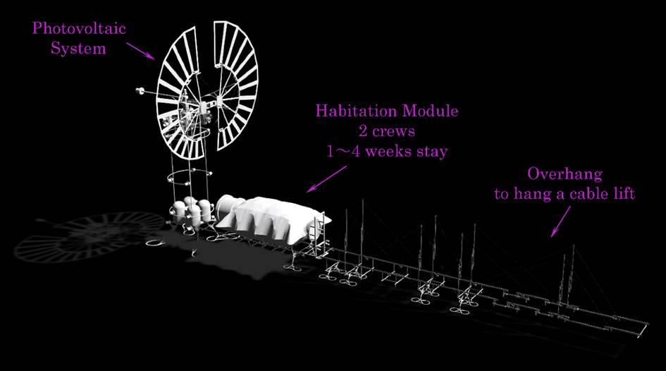
On the lunar pole, considering two crew members staying one to two weeks, an all-in-one module composed of a pillow-shaped aluminum polyhedron for habitation, a photovoltaic system, and an overhang equipped with a cable lift can be installed on the rim of a petit crater (see Fig.1).

Fig. 1. Lunar pole setup of a base camp for two crews
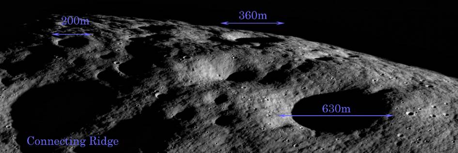
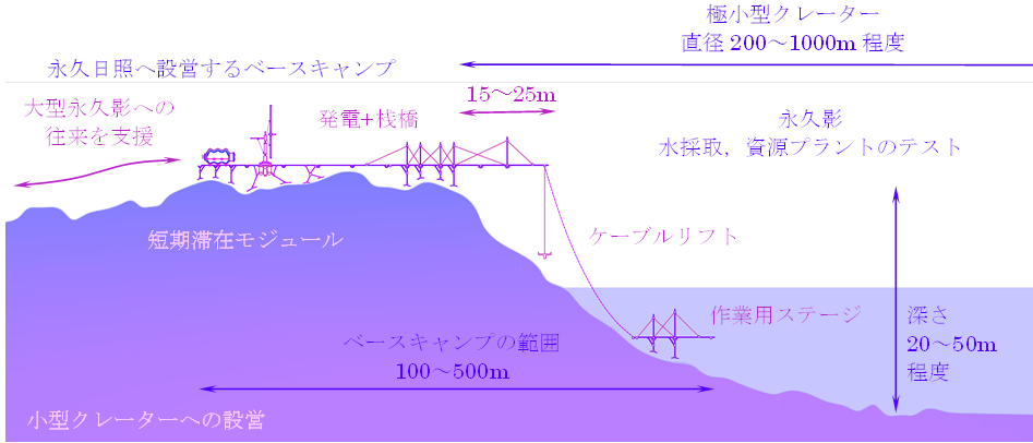
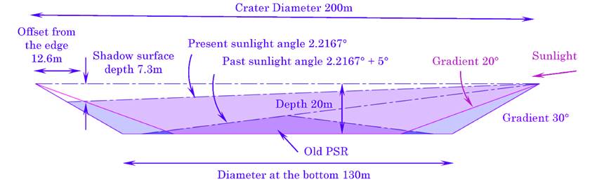
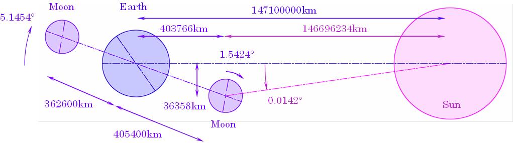
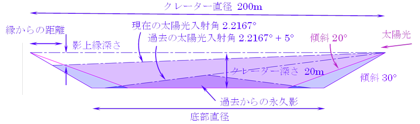
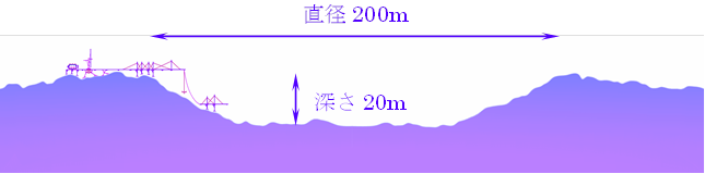
Looking at the high-resolution image of the lunar surface (see Fig. 2), petit craters with diameters of 200m to 600m can be found everywhere. Fig. 3 and Fig. 4 show the presence of PSR in the petit crater with a diameter of 200m and a depth of 20m.
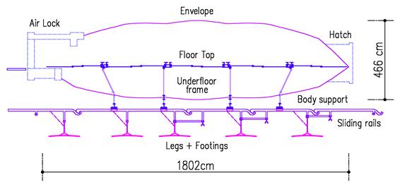
Fig. 2. High-resolution image of the moon surface
https://www.lroc.asu.edu/posts/1105
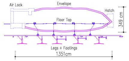
Fig. 3. Sunlight angle on the pole
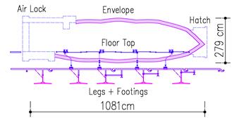
Fig. 4a. PSR in a petit crater
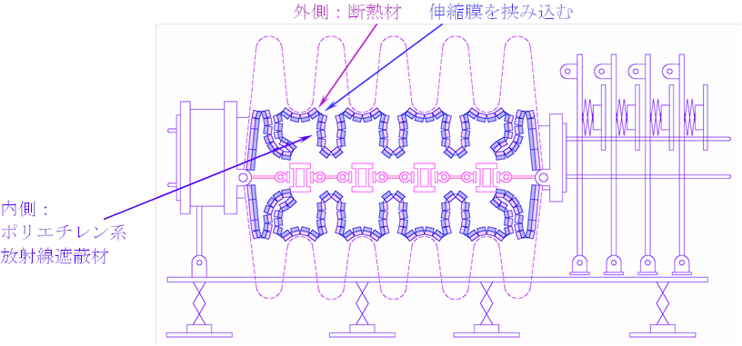
Fig. 4b. Section image of the petit crater and the base camp
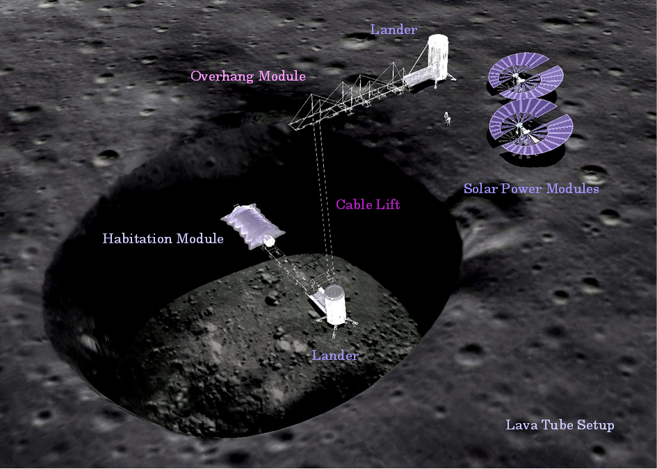
3: Lava tube setup
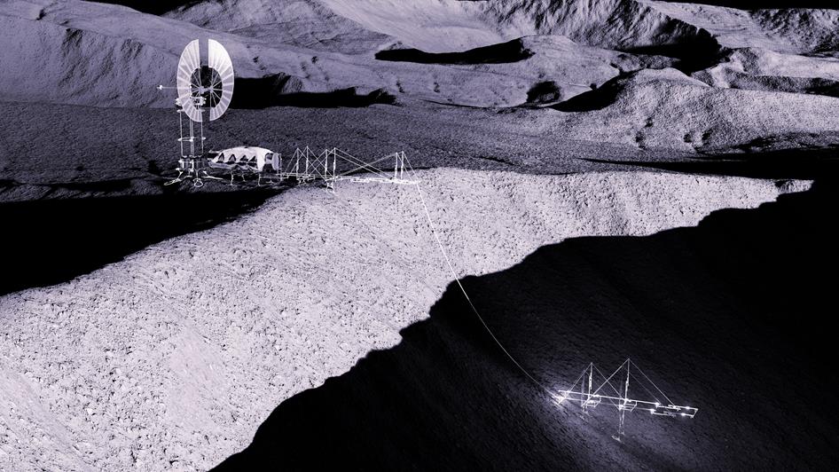
For the lava tube, supposing four crews stay four weeks to six months, the modules are split. A habitation module is implanted into the cave at the bottom, while two solar power modules and an overhang module equipped with a cable lift are installed on the edge (see Fig. 5).

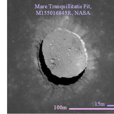
Fig. 5. Lava tube setup of a base camp for four crews
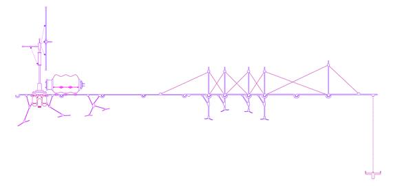
Supposing only two crews stay only one to two weeks during the daytime of the moon, the photovoltaic system becomes small enough to be composed into a single module with an overhang. Hereafter, the base camp can be built up by two transports (see Fig. 6).

Solar panel and overhang Habitation
Fig. 6. Two modules for two crews
4: Setup options
The way to combine the modules depends on the number of transports, the number of crews, and the length of stay. Envisioning a minimal setup, one to two weeks stay in the daytime of the moon, the battery cell becomes small. Hereafter, the all-in-one module (see Fig. 7) becomes 8 to 10 metric tons, excluding the landing gear.

Fig. 7. All-in-one setup for two crews on the lunar pole

Split setup for lava tube / Habitat + PV setup
5: Habitation module
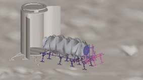
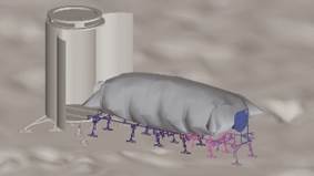
When the pillow-shaped envelope (see Fig. 8) made of aluminium inflates by internal air pressure, as shown in Fig.9, the embedded floor (see Fig. 10) deploys simultaneously, the sliding rails are ejected, and the adjustable legs touchdown on the bumpy terrain.

Fig. 8. Components of a habitation module

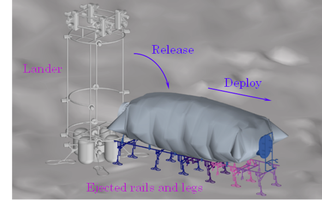
Fig. 9. Packed state / Deployment process of the habitation module → Movie
Habitation module mock-up, S=1:10


Embedded floor / Adjustable leg
Fig. 10a. Small mock-up provided in 2022 [2], S=1:10


Fig. 10b. Touchdown options
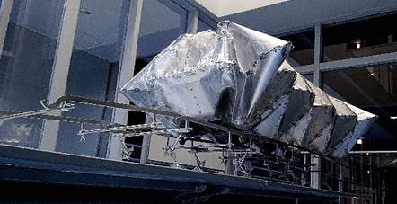
5.1: Full scale multifaceted metal envelope
As developed in 2023 [2], the envelope is folded using curved creases (see Fig 11), and Sakura dimples (see Fig.12) are scattered to snap through easily during the deployment.


Fig. 11. Folded metal polyhedron using curved creases
Fig. 12. Sakura dimples
From the overall pillow shape, a local shape, which is hardest to snap through, could be extracted, as shown in Fig. 13 and Fig.14. A full-scale mock-up of the partial polyhedron (see Fig. 15) could deploy by inner air pressure up to 0.10 atm, without fatal wrinkles even though Sakura dimples are not scattered yet (see Fig. 16).
As shown in Fig. 17, the hinges, developed referring to the zipper, could follow the curved crease during deployment.


Fig. 13. Hard snap-through spot on the overall envelope
Fig. 14. Partial polyhedron extracted from the envelope

Fig. 15. Partial polyhedron full scale mock-up, S=1:1
Material : Aluminium alloy A5052-H34, t=2.0mm


Fig. 16 Deployment Test, Partial polyhedron, S=1:1
Maximum inner air pressure = 0.10 atm
Fig. 17. Hinges for the curved crease, S=1:1
5.2: Full scale support beam
The envelope is lifted up from the rails by support frames (see Fig. 18). Taking the lunar dust into account, the sliding mechanism using cogwheels for the wheels is developed, as shown in Fig. 19 and Fig. 20.


Fig. 18. Support beam lifting up the envelope
Fig. 19. Support beam full scale mock-up, S=1:1
Fig. 20. Sliding mechanism using cogwheels
5.3: Supply packing
To make less transports, all the supplies have to be transported at the same time with the primary structure. The volume of the supplies becomes 20m3 in total for two crews staying two weeks.
The inner space of a cylinder (see Fig. 21, Fig. 22) extended from the airlock becomes 18m3 to 28m3, derived from the inner diameter of 1.82m to 2.26m, so the supplies will be able to be packed into the cylinder.

Fig. 21. Floor plan showing the cylinder filled with the supplies

Fig. 22. Elevation showing the cylinder filled with the supplies
5.4: Attachment of radiation shield and insulation
For the long stay on the pole, a laminated bag of the radiation shield tiles and the insulation tiles, with an elastic film in between, can be inflated and attached inside the envelope (see Fig. 23).

Fig. 23. Attachment of radiation shield and insulation
5.5: Interior image including dense vegetation
In the case of four crews stay six months, the interior arrangement image is developed including dense vegetation (see Fig. 24).

Fig. 24. Interior arrangement for 4 crews option including dense vegetation
(Provided by Takenaka Corporation)
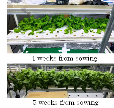
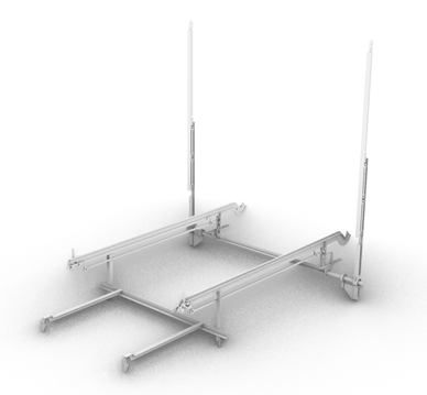
Fig.25 shows the dense vegetation image provided in 2022 [3] in the cramped side space of the pillow shape as well as the underfloor space. Assuming four crews stay more than four weeks and 40% of the food to be equipped, supposing leaf lettuce on behalf of all the plants, 9800 plants are required to build up the cycle of O2, CO2 and food. To manipulate this huge number of plants, a planter pallet (see Fig. 26) is developed. Every week, multiple plants can be slid at once by a bar to make distance of their size.


Fig. 25. Dense vegetation conceptual drawing
Fig. 26. Planter pallet developed for dense vegetation
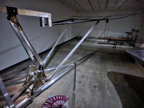
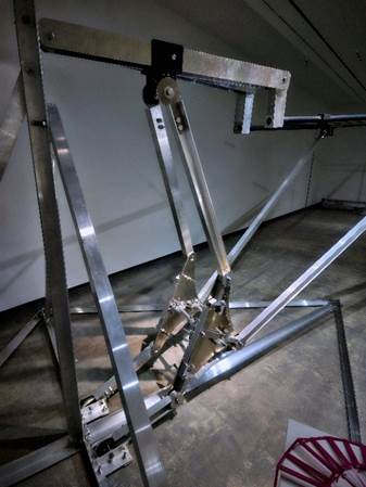
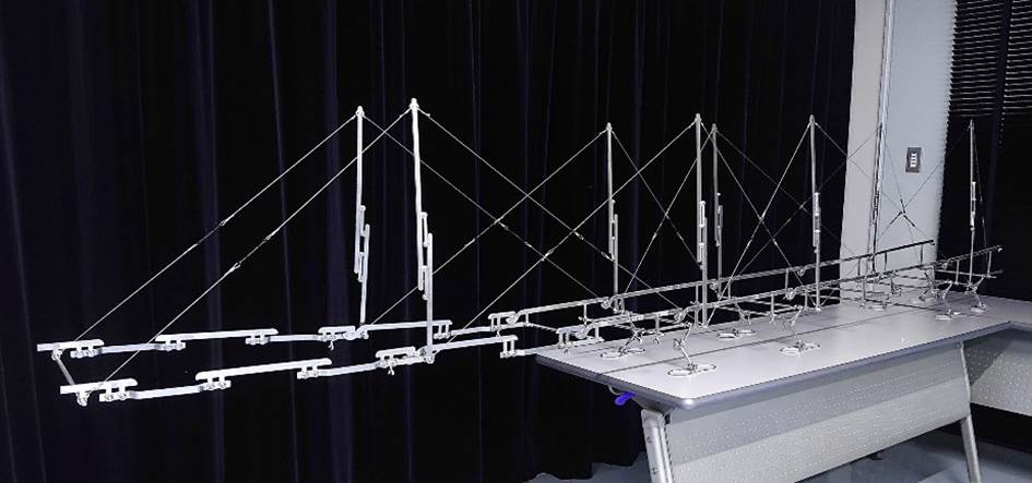
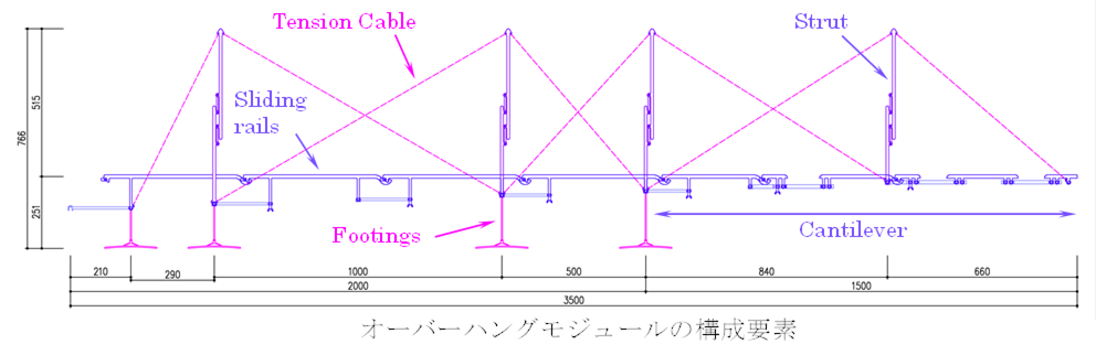
6: Overhanging suspension tectonics
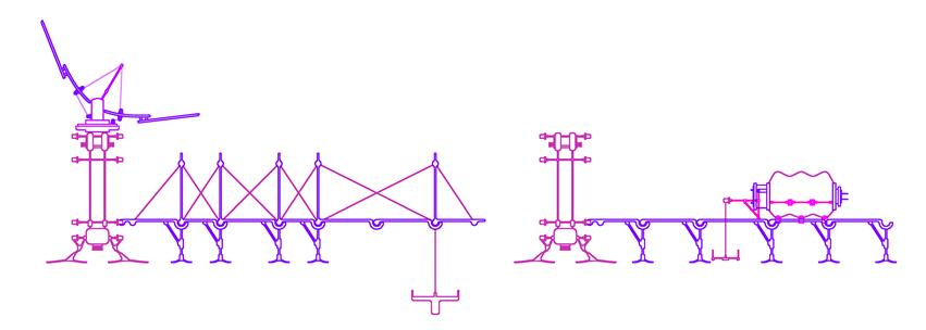
A cable lift connecting the bottom of the crater or the lava tube and the surface of the moon is hung from the cantilever around 15m (see Fig.27).
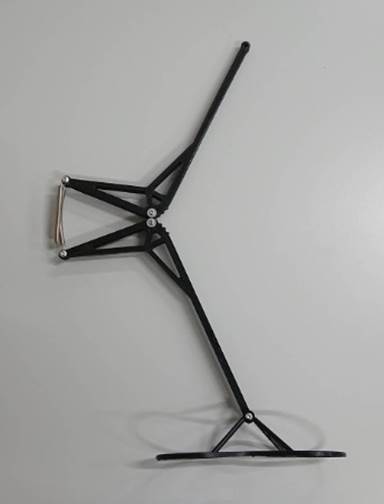
A full-scale mock-up of a single unit (see Fig. 28) shows the deployment mechanism, including the locking mechanism at the bottom of the strut (see Fig. 29) and the legs-dropping mechanism.

Fig. 27. Overhang module provided in 2022 [2], S=1:10


Fig. 28. A single unit of the overhang module image
Fig. 29. Overhang module full scale mock-up, S=1:1
Locking mechanism at the bottom of the strut
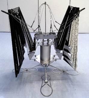
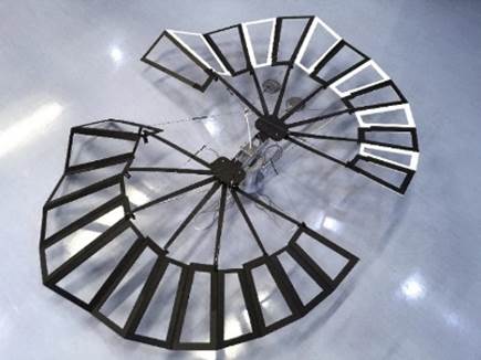
7: Fanning mechanism for photovoltaic system
For the photovoltaic panels, a fanning mechanism (see Fig.30) referring to the earwig wing has been developed by K. Saito et al. [5]. Hereafter, the full-scale partial mock-up (see Fig. 31), from which three panels out of 26 panels are extracted, supported by 3-hinge bracings (see Fig. 32), shows the deployment mechanism and the stability.


Fig. 30. Solar power module provided in 2022 [2], S=1:10 / Earwig’s wing


Fig. 31. Solar power module, full scale partial mock-up
Fig. 32. 3-hinge bracing holding three fanning panels
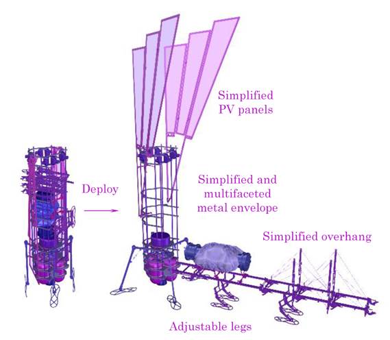
8: Tiny module for the pilot exploration
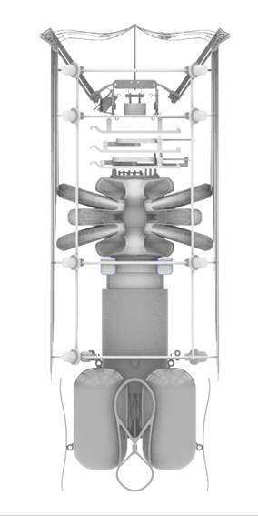
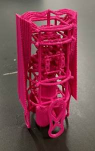
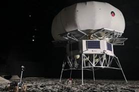
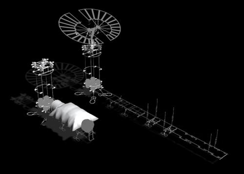
Pilot exploration is expected to be carried out over the next several years. An image (see Fig. 33) and a model (see Fig.34) show a simplified tiny all-in-one module developed to be packed into around 1.0m diameter, with a height of 2.8m, with a mass of 80 to 200 kg.
Deployment tests under microgravity and in the vacuum of space, a touchdown test on bumpy terrain, continuous electric power generation, and a test of a part of ECLSS under microgravity can be carried out in this exploration (see Fig.35).


Fig. 33. Pilot exploration module setup / Mock-up, S=1:2


Fig. 34. Pilot exploration module, 3D printed
Fig. 35. Pilot exploration module diagram
9: Habitation module references


Habitaion module for Artemis, provided by Italy & France
Interior arrangement of i-HAB, Gateway, provided by ESA
https://www.thalesaleniaspace.com/en/news/lunar-multi-purpose-habitat-activities-officially-underway
https://liquifer.com/gateway-i-hab/


Inflatable habitation modules: Mushroom / Pumpkin / Horizontal barrel
Binera/Spartan Space/Sierra Space & ILC Dover
https://ntrs.nasa.gov/api/citations/20220013669/downloads/Internal%20Layout%20of%20a%20Lunar%20Surface%20Habitat.pdf
https://actu.fr/auvergne-rhone-alpes/grenoble_38185/grenoble-il-pourrait-envoyer-cette-maison-sur-la-lune-le-projet-fou-de-peter_56390873.html
https://spacenews.com/sierra-space-tests-inflatable-module-technology/
https://spacenews.com/sierra-space-and-ilc-dover-partner-on-inflatable-modules-and-spacesuits/
This research and development are consigned as a “Project for the promotion of innovative technologies in unmanned construction applicable to the site on the moon and others” by the Ministry of Land, Infrastructure, Transport and Tourism, Japan, and the Ministry of Education, Culture, Sports, Science and Technology, Japan in 2022 - 2025.
● Development team leaders:
Jun Sato, Saneyuki Kawabata, Tomohiro Yokozeki / The University of Tokyo
Kazuya Saito / Kyushu University
Masato Ohata / Takenaka Corporation
Masato Sakurai, Yasuhiro Awata, Nao Hoshinouchi / JAXA
● Development team members:
The University of Tokyo:
Ruta Stankeviciute, Martin Ivanov, Yuta Shimoda, Shimpei Kojima, Keiichi Kutomi, Ayumi Sakamoto, Keiichiro Suzuki, Kengo Yagi, Kosei Atarashi, Tomoya Uchida, Wataru Nakayama, Issei Hirabayashi, Izumi Sato, Motoharu Iwasa, Yu Okumura, Yuki fujita, Takuma Kato, Shota Kawahara, Iuko Tsuwa, Hiromi Ishii
Takenaka Corporation:
Shou Tanaka, Tatsuho Sato, Ryuuya Matsuoka, Hideaki Tani, Atsushi Mizutani.
Mock-ups are provided by:
ROSSO Co., Ltd., Obata Co., Ltd., Suzuki Kinzoku Co., Ltd., Sakase Adtech Co., Ltd.
Deployment test is provided by:
BRAVO Co., Ltd.
● References
[1] J. Sato, S. Kawabata, T. Yokozeki, K. Saito, M. Ohata, M. Sakurai, Y. Awata, N. Hoshinouchi: Quick Setup Mechanism for Lunar Base Camp on the Pole / in the Pit, International Astronautical Congress (IAC), A3, IP, 223, x88668, 2024
[2] J. Sato, S. Kawabata, T. Yokozeki, K. Saito, M. Sakurai, Y. Awata, N. Hoshinouchi: Passive Deployment Mechanisms for Minimal Composition of Lunar/Martian Base Camp Implanted into Lava Tube, 52nd International Conference on Environmental Systems (ICES), 2023, 233
[3] J. Sato, S. Kawabata, L. Tenorio, J. Yazawa, A. Yukawa, Y. Awata: Quick Setup Lunar/Martian Base Camp Implanted into Lava Tube Derived from Jasmine Dimples and Low Curvature Folding. International Astronautical Congress (IAC), 2022, LBA-A3-3-x74519
[4] J. Sato: Quick setup Base Camp composed of simultaneously deployable surface and floor, 2H02, 65th Symposium on Space Science and Technology, Yamagata, Japan, 2021
[5] K. Saito, R. P. Fuente, K. Arimoto, Y. Seong, H. Aonuma, R. Niiyama, Z. You: Earwig fan designing: Biomimetic and evolutionary biology applications, The National Academy of Science, 117(30), pp.17622-17626, 2020